
If a toolbar or a window is hidden, use the View menu to find it and show it in the application window.
Home > Getting Started > Create a Map, Diagram, or Flowchart > Place and Connect Shapes
This topic is based on having a Cross Functional Process diagram open.
See Placement Shortcuts for more placement options, such as how to automatically connect placed shapes.
Click a shape in the Toolbox toolbar (on the left side of the application window). Then, with your cursor inside the Start shape in the diagram, press and hold your mouse button (click and drag) to the desired location and release the mouse button to drop the shape into place with an automatic connector from the Start shape. See the iGrafx Tutorials for more information about placing shapes.
|
|
If a toolbar or a window is hidden, use the View menu to find it and show it in the application window. |
You can also place a shape from the Shape Palettes window (by default, on the right side of the application window) in the same manner.
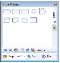
Shape Palettes window |
If the Shape Palettes window is hidden, on the View menu, choose Shape Palettes or click the  button on the Standard toolbar.
If the desired shape palette is open but not visible, click the specific shape palette tab in the Shape Palettes window.
|
|
Click View at the bottom of the Shape Palettes window to control the display of shape images and shape names in the window. |
If the desired shape palette is not open, click the  tab or click the
  button on the toolbar at the bottom of the Shape Palettes window.
In the Choose Shape Palette dialog box, double-click to open the palette you want. If you have multiple palettes open at the same time, they display as vertical tabs at the top right of the window.
For information on how to create and manage shape collections, see Shape Palettes Procedures.
For information on how to customize diagram appearance with colors, see Add Styling to Diagram Objects.
|
|
Copy the formatting of selected text, shapes, or lines to other objects in one step using the Format Painter tool on the Standard toolbar. |
Related Topics
See Also

