This section discusses only those swimlanes that appear in diagrams. In addition to those in diagrams, other swimlanes may be defined by the Define Resources dialog box for simulation use.
Home > Swimlanes and Floating Swimlanes Procedures
Swimlanes and Floating Swimlanes Procedures
|
|
This section discusses only those swimlanes that appear in diagrams. In addition to those in diagrams, other swimlanes may be defined by the Define Resources dialog box for simulation use. |
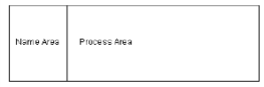
Swimlanes are visual containers that designate separate operations within a process. Each swimlane is divided into a name area and a process area.
|
|
To manage swimlanes, on the Arrange menu, choose Swimlanes. You could also click the  tool on the Toolbox toolbar. The Swimlane Manager helps manage multiple swimlanes with complex hierarchy. You can also use it to add or remove one swimlane at a time.
By default, BPMN diagrams use pools, which are floating swimlanes. Key differences between swimlanes and floating swimlanes are:
Swimlanes are connected together with no space between swimlanes; top-level floating swimlanes are separated from one another by white space.
Shapes can span across multiple swimlanes. You cannot place shapes between floating swimlanes or spanning two or more floating swimlanes.
Lines can connect shapes between floating swimlanes, but in a BPMN diagram, connector lines are translated into message lines that do not simulate a flow.
Related Topics
Overview Topics